Case Study: Using VFDs to Control Water Pressure in Municipal Pump Stations
Small municipal water utilities face increasing pressure to reduce energy use, maintain stable system pressure, avoid bursts and downtime, and operate pumps efficiently. In this case study we show how a mid-sized water utility achieved a 22% reduction in energy cost and improved system reliability by upgrading to variable frequency drives (VFDs) on their booster pump station.
We’ll cover the initial challenge, the solution design, implementation details, measured outcomes, and lessons learned — including links to engineering tools such as the VFD Sizing Calculator, VFD Cable Sizing Calculator, Braking Resistor Calculator, and Motor Starter Selection Calculator.
Background: Pressure Instability & Energy Consumption
The pump station supplies water to a town of ~30,000 residents via two 75 kW booster pumps. Previously, the system ran at full speed via direct-on-line starters, controlling pressure via a throttle valve and on/off cycling. The main issues were:
- ⚠️ Pressure spikes when pumps switched on/off — causing pipe bursts and consumer complaints
- ⚠️ Energy waste with oversized pumps running at full speed during low-demand periods
- ⚠️ Frequent start-stop cycles leading to mechanical wear and increased maintenance
Energy audits indicated that the pumps accounted for roughly **40% of the facility’s total electricity consumption**, making them a logical target for optimisation.
Project Objective
- 🔹 Replace legacy control with variable speed control to maintain stable system pressure
- 🔹 Reduce energy use by at least 15% within the first year
- 🔹 Improve system reliability and reduce bursts/maintenance events
- 🔹 Provide real-time monitoring of pump status and system pressure
Solution: VFD Implementation on Booster Pumps
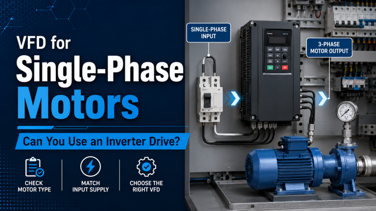
The water utility selected two key VFD units for the upgrade: – :contentReference[oaicite:0]{index=0} – used on one booster pump, offering single-phase input to three-phase output and built-in pump/fan functions. – :contentReference[oaicite:1]{index=1} – used on the second pump, a compact three-phase drive with pump library and intelligent control.
Key features utilised included:
- ✔ Closed-loop pressure control via pressure transducer feedback
- ✔ Variable speed to match system demand instead of full speed + throttle
- ✔ Ramp-up/down to eliminate pressure surges on start/stop
- ✔ Built-in motor protection reducing wear and failure risk
Design & Sizing Considerations
Using the VFD Sizing Calculator, engineers confirmed that each drive rating matched the motor’s full load current, with 10% headroom for duty. They selected cable sizes and shielded runs via the VFD Cable Sizing Calculator to maintain voltage drop <3 % and prevent EMC issues.
Since the system had long motor-cable runs of ~45 m each, extra emphasis was placed on cable routing, shield terminations and grounding to ensure reliable drive operation in a wet pump-station environment.
Installation & Commissioning
The installation took place over a weekend to avoid service interruption. Old starters and throttle valves were bypassed. Drives were installed in IP54 enclosed cabinets with proper ventilation. Pressure sensors were fitted to the delivery line and wired into the drive’s analogue input for closed-loop control.
Commissioning included:
- ✅ Motor auto-tune on each drive
- ✅ Pressure loop tuning for minimal overshoot < 5 psi
- ✅ Verification of ramp times (start: 8 s, stop: 10 s) to reduce surge
- ✅ Real-time monitoring enabled via SCADA for speed, current, pressure and fault codes
Results After Six Months
| Metric | Before Upgrade | After Upgrade |
|---|---|---|
| Energy Use (kWh/month – pumps only) | 28,000 kWh | 21,840 kWh (−22%) |
| Pressure Surge Events (burst/maintenance) | 6 per year | 2 per year (−67%) |
| Peak Current on Start | 450 A | 230 A (−49%) |
Operators also reported smoother start-up and near-elimination of pressure spike complaints from consumers.
Maintenance & Reliability Gains
With VFD-based control:
- 🔧 Bearing & seal failures reduced due to fewer hard starts
- 🛠 Maintenance calls for pressure surges dropped significantly
- 📉 Motor and drive fault alarms integrated into SCADA allowed earlier detection
Energy Efficiency & Cost Savings
Assuming an electricity cost of £0.14/kWh, the monthly savings (~6,160 kWh) equates to ~£860 per month, or £10,300 per year. The reduction in maintenance and burst-repair costs adds additional value — estimated at an extra £4,500 annually.
Project cost (hardware + installation): ~£43,000. Simple payback ≈ 3.4 years, ROI over 5 years > 150%.
Control System Integration
The drives were connected to the station’s SCADA system via Modbus RTU. Real-time data such as motor speed, current draw, pressure set-point and fault codes are displayed on the control screen. This allows remote monitoring and automated logging of service intervals.
Lessons Learned
- 🔹 Proper drive selection for pump duty is critical – choose “pump/fan” libraries when available.
- 🔹 Cable routing and EMC considerations matter for reliable operation in pump-station environments.
- 🔹 Ramp times must be tuned to avoid hydraulic shock or pipe bursts.
- 🔹 Analytics from the drive and SCADA help drive continuous improvement.
Conclusion
This case study demonstrates how applying VFD technology in a municipal pump station brought measurable improvements in energy efficiency, pressure stability, and maintenance savings. By replacing standard starters with modern drives and closing the control loop with a pressure sensor, the utility achieved significant gains.
If you manage pump stations, booster sets or water distribution networks and are considering a VFD upgrade, we recommend starting with the free tools below and consulting with an experienced drive partner:
At Drive Outlet Megastore, we supply a wide range of VFDs—including industry-leading models such as the Invertek Optidrive E3 and Schneider Altivar-312—fully stocked in the UK. Contact our team today for pricing, sizing help or technical support.